Shipping Options

View more details in our Shipping Policy

All shipping rate advertisements assume delivery to continental US address, and that the part is in stock and is not oversized.

Shipping rates are per order, not per part!

Standard – $10.99
Estimated arrival
Tuesday Apr 23–26
Quicker – $24.99
Estimated arrival
Tuesday Apr 23
Quickest – $33.99
Estimated arrival
Monday Apr 22

Appliance Repair Blog

How To Test a GE Refrigerator Thermistor Sensor WR55X10025

Posted on July 11, 2014

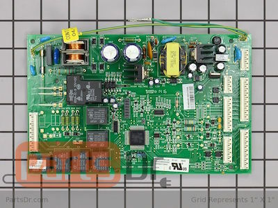
Some newer GE model refrigerators manufactured after 2002 use a thermistor in the refrigerator and freezer sections to control the temperature and the automatic defrost cycle. The thermistor is a variable resistor that varies its resistance depending on the temperature. It is sometimes referred to as a temperature sensor. GE used these thermistors on some Side-by-Side, bottom freezer, and top freezer refrigerator models that use a main control board on the back of the refrigerator. The main control board monitors and reads all of the thermistors to properly control all of the functions of the refrigerator. Please note that all of the thermistors on these models are the same.

**Before working on your refrigerator, make sure the refrigerator is unplugged.**

Thermistor Locations & Functions

Refrigerator Section: The refrigerator may have one or two thermistors located in different areas to monitor the temperature in the refrigerator section. These sensors send their signal to the main control board, which may turn on/off the compressor or evaporator fan motor, or open/close the air damper to let more or less cold air into the refrigerator compartment. When one of these sensors fails, it can cause the temperature to be off or even cause the refrigerator not to run (not very common).

Freezer Section: The freezer section has one thermistor sensor, not including the thermistor on the evaporator coil (see below). This sensor sends its signal to the main control board which may turn the compressor on/off or turn the evaporator fan motor on/off. When this sensor fails, it can cause the temperature to be off or even cause the refrigerator not to run (not very common).

Evaporator Coil: The evaporator coil (located behind the back panel in the freezer section) has one thermistor sensor attached to the top side of the evaporator coil. The control board monitors this thermistor and uses it to know when to go in and out of the automatic defrost cycle. Some people refer to this thermistor as the defrost sensor. This is the most common sensor to fail because it is subject to extreme temperature changes and moisture. When this sensor fails it can cause the refrigerator to not go through the automatic defrost cycle properly. When replacing this sensor, you must first manually defrost the evaporator coil to get it caught back up for the refrigerator to continue to work properly going forward.

Old Style Vs. New Style Thermistor

Some refrigerator manufactured 2005 and earlier may have a thermistor design that is prone to failure. The differences between the old and new style thermistor is easy to spot. The old style thermistor has a black area around where the wires come out of the sensor and it also has a rounded tip. The new style sensor is white around where the wires come out of the sensor and the tip of the sensor is flat. If your refrigerator has the old style thermistor sensors, then you should change out all of the thermistors with the new style sensor.

The old style thermistor is pictured on the left with a round tip and the new style thermistor is pictured on the right with a flat tip.

WR55X10025

The old style thermistor is pictured on the left with a round tip and the new style thermistor is pictured on the right with a flat tip.

WR55X10025_2

How To Test The Thermistor

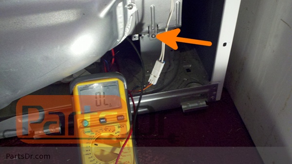
You can test your thermistor(s) using an ohm meter or multi-meter. The best way to do this is to remove the thermistor from the refrigerator so you can control the temperature of the sensor. You can let the sensor warm up to room temperature or grab a glass of ice water to test the thermistor. With the sensor warmed up to room temperature the sensor should read approximately 6.2K Ohms at 68°F. With the thermistor submerged is a glass full of ice water, the sensor should be very close to 32°F which should read approximately 16.3K Ohms. If the values that you are getting are far off from these readings, then the sensor is bad and should be replaced. If the reading you are getting is not consistent; where sometimes the ohm reading is correct and other times it isn’t, even though the temperature hasn’t changed, then the thermistor should be replaced.

Where to Buy

The common thermistor used on some GE refrigerators is part number WR55X10025. Thermistors are model specific and should be verified with the model number of the refrigerator before ordering. This is the newest version of this part, and has been improved to have less problems. Click the link below to visit our store to purchase a replacement thermistor sensor.

Temperature Sensor (Thermistor) – Part # WR55X10025

Do I Need The DA81-01421A Ice Maker Kit?

Posted on

A common question that we frequently get asked by our customers is whether they can just replace their ice maker (part number DA97-05422A), or if they need the kit that includes the ice maker and main control board (part number DA81-01421A).  Please note that the ice maker and control board kit only works with the four model numbers listed below and it does NOT work with any GE refrigerator models.

Ice Maker Symptoms

The ice maker and control board kit may take care of one or more of the following symptoms:
  • No or low ice production.
  • Ice cubes jamming between the ice tray and the liner of the refrigerator.
  • A clicking or grinding noise coming from the ice maker.

Model Numbers Affected

If your model number is one of the four models list below, then you may need to replace to replace the main control board along with the ice maker at the same time.  See below on how to check the software version.  If your model is not listed, then you already have the newer software, and the main board is not required to be replaced at the same time as the ice maker.
RF267AABP, RF267AARS, RF267AASH, RF267AAWP

Check the Main Control Board Software

To check the software version of the main control board, you will need to unplug the refrigerator and remove the cover to the main control board on the back side of the refrigerator.  On one of the main processors there will be a sticker.  If the software version is lower than 4.02 or the sticker is white in color, then you need to order the DA81-01421A kit and replace both the control board and the ice maker.  If the software version is 4.02 or higher, or the sticker is red in color, then you have a newer version main control board and it does not need to be replaced when replacing the ice maker.

Software Sticker

Where Can I Buy A Replace Ice Maker & Control Board Kit

You can buy a replacement GE or Samsung ice makers from our online store.  Please click the link below.  Parts Dr always has the lowest prices for new O.E.M. replacement parts.

Ice Maker & Control Board Kit – DA81-01421A
DA81-01421A-1

Ice Maker – DA97-05422A (Same Ice Maker as included in the above kit, but without main control board)

Questions Or Comments?
If have any questions or comments please post them in the comments section below.

How To Install Samsung Dryer Heating Element DC97-14486A

Samsung dryer heating element DC97-14486A is used on many Samsung clothes dryers and even some Maytag (Neptune) and Amana dryer models.  When the heating element goes bad, it will usually have a break in the heating coil which will cause the element not to heat.  These instructions work for most Samsung dryers, some may have some small differences but the overall process if very similar.  Here is how to replace and test the DC97-14486A & DC47-00019A heating element:

First, unplug or shut off the power to the dryer before working on it.

How_to_remove_samsung_dryer_heating_element_DC47-00019A

Then remove the two screws securing the top panel to the back of the dryer.  Slide the top panel towards the back of the dryer to remove.  Now you will need to remove the front control panel, some model will have screws securing this. Remove them and then pull up to remove, you should have enough extra wire to set the control panel on top of the dryer to get it out of the way (if not, then disconnect the wires and set it off to the side).

Behind where the control panel was there will be four screws that secure the front panel of the dryer to the frame.  Remove these four screws.

How_to_remove_samsung_dryer_heating_element_DC47-00019A_2

Open the door of the dryer, there will be two screws that need to be removed at the bottom of the door frame area.  With those two screws removed you should be able to tilt the front panel forward, remove the connector to the door switch, and remove the front panel.

How_to_remove_samsung_dryer_heating_element_DC47-00019A_3

The heating element is located on the bottom right side of the dryer.  To remove the element you will need to remove the wires to the heating element, thermal fuse, and thermostat.  Then remove the mounting screw in the front and the whole heating element assembly should pull out the front of the dryer.

How_to_remove_samsung_dryer_heating_element_DC47-00019A_4

To test the heating element, you will need an Ohm meter or multi-meter.  A good heating element should read approximately 9-10 ohms.  A burned out element will have an infinite resistance (it won’t register anything).  See the video below for instructions on how to test the heating element.

To re-install the heating element you will need to put everything back in the reverse order.  If you lost track of how the wires connect to the heating element, please see the picture below.

DC97-14486A Wiring WM

If you need to purchase a new Samsung dryer heating element, click one of the two links below.

The best way to purchase the heating element is as an assembly. The heating element assembly includes the heating element, two thermostats, and housing.

Heating Element Assembly –  Part # PD00002003 (mfg # DC97-14486A)

We also sell the heating element by itself.  You will need to re-use the thermostats and element housing.

Heating Element – Part # PD00001991 (mfg # DC47-00019A)

Dryer Maintenance Tips

Maintaining your dryer properly can be the difference of saving yourself hundreds of dollars of repair costs over the lifetime of your dryer.  Not keeping your dryer lint free can not only cause your dryer to break down more, but the lint build up is a serious fire hazard.  Here are 4 things to check.

Lint Filter

Clean the lint filter for the dryer after every load.  If you see any tears or rips in the lint filter, replace the filter with a new one.  Any large holes in the lint screen will allow lint to get past the filter and prematurely clog up the inside of the dryer or the exhaust vent.

Blower Housing (Area Under Lint Filter)

The area underneath the lint filter is typically called the blower housing.  The blower housing is a main air duct where air flows through your dryer.  Often, lint will build up in this area and it will need to be cleaned out.  On some dryers you can use a small brush to stick into the lint filter opening to clean out the lint, and on other dryers the whole dryer has to be taken apart to clean out the blower housing.  This is important to keep clean to maintain good airflow in your dryer.

Dryer Vent

Over time,  and even when cleaning the lint screen every load, a small amount of lint still passes by the lint filter and some of it builds up inside your dryer exhaust vent.  This lint needs to be cleaned out either by taking the venting apart (if accessible), or by hiring a professional company to clean your vent out.  Always make sure to use metal venting.  Plastic flexible venting can cause fires, and should be replaced with new aluminum venting.

Dryer Cabinet

The inside cabinet of the dryer will build up with lint over time.  This usually doesn’t accumulate very fast, but if you have an exhaust vent that is not sealed up very well then a lot of that lint can circulate back into the dryer.  Before pulling your dryer apart, make sure to unplug it first.  Some dryers have a front bottom panel that is removable that will give you easy access to cleaning out the cabinet of the dryer.  Other dryer models have to be pull completely apart to accomplish this task.  If you aren’t very handy, you may need to hire a appliance repair man to do the job for you.

How To Install GE WR55X10942 Main Control Board

Installing and replacing the WR55X10942 GE Refrigerator Main control board is an easy task and normally only takes about 15 minutes.  The main control board is located on the back side of the refrigerator behind a cover panel.  This circuit board controls almost all of the functions on the refrigerator.

This is how to replace the control board:

First unplug the refrigerator.

Next remove the screws securing the cover on the back side of the refrigerator.

Then remove the two bottom electrical connectors.

Next you will need to remove the control board from the plastic pins that secure the board to the refrigerator.  Push in on the side of the pin (or squeeze it with a needle nose pliers)  while gently pulling out on the control board at the same time.  Most boards have 4 – 6 pins that secure the control board.

Now pull the old control board off to the side and place the new control board in its place.  Make sure all the plastic pins secure the new board into place.  Now you can start transferring the wiring connectors from the old board to the new control board.  Don’t forget to plug in the two bottom connectors that you removed earlier.

Here is the new board all hooked up.

Please note that on some models you may have left over spots where you will not have any connectors to plug into them.  This is normal.  All of the plugs have different amounts of pins, so if you are unsure where a connector goes, you can count the pins to match up where it should go.

Included with your new control board is an instructions sheet.  Please read through this sheet completely and follow any steps that apply to your model.  These changes affect some side by side and some bottom freezer models.

If your model has a wire going into pin 2 on the 9 pin connector, you will need to cut this wire or you refrigerator section will not cool down to the proper temperature.  Check your model/serial number to see if yours is listed on the instruction sheet. (Note:  I have also seen models that were not listed on the sheet that needed to have this wire cut also).

On some bottom freezer models you may also have to cut a green wire.  Please follow the instructions included with the control board to see if your model requires this.

Re-install the back cover panel on the refrigerator, make sure the ground wire from the control board is grounded to one of the screws.

Plug in the refrigerator and test to make sure it is operating properly.

If you need to purchase a control board for you refrigerator please click the link below to visit our parts store.  We usually have the lowest price on the internet for these control boards.  If you have any questions or comments please post them in the comments section below.

GE Refrigerator Main Control Board – WR55X10942P

How To Remove & Install 131763202 Door Lock Latch

The Frigidaire door lock/latch 131763202 has been used on many different models of washers over the years.  Removing and installing this part is an easy that only takes a few minutes. No need to call Keys 4 The City locksmiths or a repair service, you can handle this one. These are some of the symptoms you can experience when the door latch/lock fails:  door won’t lock, door won’t unlock, E47 error code, agitates but won’t spin, and more.

Here is how to replace the door lock/latch assembly:

Always unplug your appliance before working on it.  First open the door and remove the two phillips screws.

Next remove the door boot seal clamp and peal back the door boot to give you access to the door lock.  You should be able to pull the door lock out and remove the three wire connectors that plug into the door latch.

Re-install the parts in the reverse order and test out the washer to make sure that it is operating correctly.

If you have a bad door lock/latch and need to purchase a new one, click the link below:

Door Lock Latch/Switch Assembly – 131763202

Frigidaire & Kenmore Garage Refrigerator Heater Kit 5303918301

Frigidaire and some Kenmore refrigerators offer a garage heater kit to keep the refrigerator operating at temperatures down to 34°F.  Without the garage heater kit, the manufacturer states that the refrigerator may not work correctly at temperatures below 55°F (13°C).  So if you plan to keep your refrigerator in a cold garage in the winter time or any other unheated area, you will want to install the garage kit that Frigidaire/Kenmore offer to keep your refrigerator working properly.  The garage heater kit is installed in the refrigerator section next to the thermostat & defrost timer.

Note: This is not designed to work with side-by-side, counter-depth refrigerators, models with electronic controls, or those made before 2001.  Only top freezer refrigerator models can use this heater designed for those put in garages or basements where the temperature drops to 34 degrees Fahrenheit.

The manufacture part number for the garage kit is 5303918301, and it can be purchased from our online store by clicking the link below:

Garage Refrigerator Heater Kit – MFG Part # 5303918301 (Part # PD00000271)

Before working on your appliance, make sure that it is unplugged.  Below are step by step instructions on how to install the garage heater kit.
5303918301_1
5303918301_2
5303918301_3
5303918301_4

How To Remove & Install Drain Pump W10536347

Removing drain pump part number W10536347 is a simple task.  When this pump fails, the washer will display “LD” on the display which means “Long Drain”.  This pump can be found on Whirlpool Cabrio, Maytag Bravos, and Kenmore Oasis model washing machines.  The pump can fail if something gets stuck in the pump (coin, clothing item, ect), and sometimes you can get lucky and just remove the object that was stuck in the pump.  Other times the pump can break, so make sure so inspect the pump before putting it back in the washer.

How to the remove the drain pump:

  1. Unplug the washer
  2. Next, you will need to remove any water still in the washer (use a wetvac, bucket, towels, ect to do this)
  3. Turn off the water supply going to the washer & disconnect the hot & cold fill hoses to the washer
  4. Remove the drain hose from the wall or drain tub
  5. Tape the lid shut (so the lid doesn’t pop open)
  6. Carefully lay the washer down on its front side (place some towels or rugs on the floor to protect the washer).
  7. Note:  On the bottom side of the washer, the drain pump is the larger of the two pumps (the recirculation pump is the smaller one).
  8. Remove the drain hose (discharge hose) from the pump.  Loose then clamp and pull off the hose.  Note there is a notch in the hose to line up when you put the hose back on.
  9. Remove the inlet hose to the pump.  Loosen the clamp and remove the hose from the pump.
  10. Open the end cover on the pump and remove the wire connector.
  11. Remove the three 5/16″ screws securing the pump.
  12. The pump should now be free.  Check to see if anything is caught in the impeller.  If you notice any damage, or the pump still does not work then you will need to replace the drain pump assembly.
  13. Re-install in the reverse order.  NOTE:  The new pump includes a shield cover that goes between the pump and tub of the washer to protect the pump from any moisture falling onto it.

If you have any questions please post them in the comments section below.

If you need to purchase a new drain pump for your washer, visit our store by clicking the link below:

Drain Pump and Motor – W10536347

How To Install & Remove W10189966 Control Board

Removing and installing the W10189966 motor/machine control board in your washer is an easy task.  This control board is used on some Whirlpool Cabrio, Kenmore Oasis, and Maytag Bravos model washers.  When this control board fails, they will commonly come up with an F1 error code repeatedly that won’t go away.

  • First unplug the washer
  • Next, remove the three hex screws from the rear of the top console.
  • Then Lift the console off the cabinet and disconnect the cable going to the user interface board.  This will give you access to the motor/machine control board.
  • Disconnect the nine wire connectors going to the control board and the pressure switch hose (also called a pressure transducer tube).
  • Remove the mounting screw and lift the front of the control, slide it out from under the clips at the back, and remove it.
  • Re-install the new control board in the reverse order.

If you have any questions, please post them in the comments section below.

Visit our store if you need to purchase a new control board for your washing machine by clicking the link below:

Machine/Motor Control – W10189966

How To Test Maytag Thermistor WP35001191

Some Maytag Neptune dryers use a thermistor temperature sensor to measure the temperature of the air in the dryer.  When this sensor fails you can get a “tS”/”t5” error code which indicates a thermistor short.  Testing this sensor is very easy, all you need is a digital mulit-meter that can read ohms.

This is how to test thermistor part number WP35001191:

  • With the thermistor removed from the dryer set your meter to measure ohms (or to the 20K/40k ohms setting)
  • Place one probe on each terminal of the thermistor
  • The thermistor at room temperature should read approximately 10k ohms.  If it is far off from that, the sensor will need to be replaced. (sensor in the above picture is a bad sensor)
  • Once the bad sensor has been replaced, you will need to reset the code or else the TS code will continue to display.

Here is how to get into service mode to clear the TS code:

  • First, Enter Service Mode.  Dryer must be on before Service Mode can be entered. Press Chime and Temperature Keys for 3 seconds, or until 3 beeps are heard. The machine will now be in Service Mode.
  • Next, access diagnostic codes by entering the Service Mode and pressing Wrinkle Prevent. A “d” will be displayed. Rotate the Cycle Selector Knob in either direction to step through the list of codes one code at a time.
  • Then, to clear the diagnostic code list press the Sensor Dry Level and Time keypads together for 3 seconds while viewing the list. The cycle count for each diagnostic code will be reset to 0, but not the machine cycle count.
  • Finally exit service mode by pressing the OFF key or repeat the Chime and Temperature sequence.

If you need to purchase a thermistor sensor for your dryer click the link below:

Thermistor – WP35001191

Parts Dr

Our customers matter a lot to us! So we provide YOU with as much information on repairing your appliance as possible. And its all FREE!

Categories

Locate Model Number

Choose your appliance type